
If you have ever dealt with a multi-switch MDS fabric, I bet you would have configured and used Port Channels (PC) on the Inter-Switch Link (ISL) connecting two switches. PCs are used to combine multiple physical ISLs between MDS switches into one logical ISL. The MDS PC configuration guide gives exhaustive details on configuration, restrictions, best practices etc. It mentions the advantages of PC as “provide higher aggregated bandwidth, load balancing, and link redundancy”. In this post I will do a bit of deep dive into these three advantages of PCs that are not covered in the config guide in detail. This post will provide you some insights into internal workings of a PC.
I assume you have basic familiarity of Fibre Channel (FC). Let us now start looking into the advantages
1) Increased aggregate Bandwidth
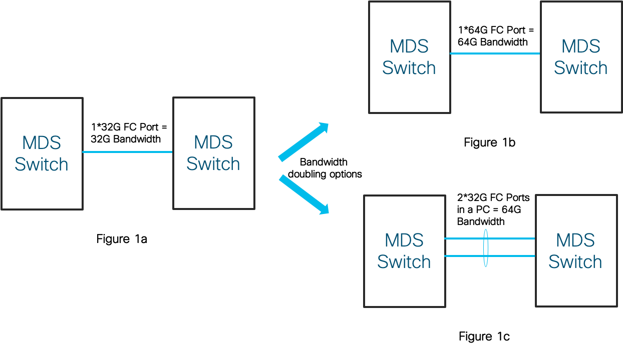
This one should be quite straight forward. When you want to increase bandwidth capacity of an ISL, there are essentially two options: either upgrade the native link capacity to a higher speed or form an aggregate of two or more lower speed links. The FC hardware (especially optics) of the next speed generation is usually significantly higher priced (>2x) than the current generation. It may even require an upgrade of the switch hardware. Hence link aggregation (with PCs) on existing hardware can be significantly cheaper and as effective as single link of higher speed on next-gen hardware. An example of this is shown below in Figure 1. You might wonder what if in Figure 1c it was not a PC? Would that not also be same? Hold on to that question, since its coming up later back to you!
2) Better Load Balancing
The links of the PC are also called as its members. Once a PC is formed, we need a Load Balancing (LB) algorithm that would pick which member to use for transmitting a frame. In general, a good PC LB algorithm would distribute the frames destined towards a PC equally among all the members. It may seem like a frame by frame load balancing (On a two member PC: Frame1->Member1, Frame2->Member2, Frame 3->Member1, Frame4->Member2 and so on) would work best, but is not suitable here.
As a quick recall from one of my earlier post, FC has a specialized construct called an Exchange and an I/O operation (Read/Write) consists of Request and Response IUs within an Exchange. The SourceID(SID) and DestinationID(DID) along with ExchangeID (OXID) contained in the FC header uniquely identifies an Exchange. The FC standards also require an In-Order Delivery (IOD) of frames within an exchange. This helps end-devices to avoid reassembly of frames to reconstruct the exchange in correct order and improves the overall I/O performance.
If a frame by frame LB were to be done, ensuring ordering of frames within an exchange becomes extremely challenging. It would require exactly identical set of characteristics on the PC members all the time to ensure latency for frame transmission on any member is a constant and PC itself does not cause any frame reordering. This means PC members having exactly same cable lengths, same levels of congestion, ports belonging to the same ASIC port-group etc. Meeting all these requirements simultaneously is quite impractical in a real world scenario. It can also result in a single failure domain, defeating the resilience aspect of the PC. Hence frame by frame LB is extremely restrictive and goes against the FC design principles of avoiding single point of failures.
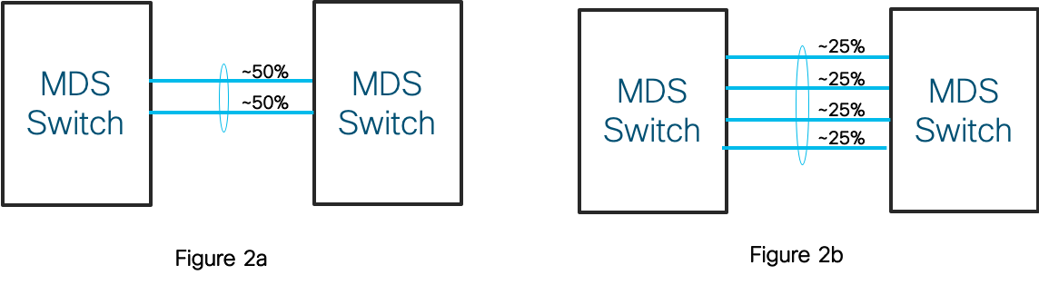
MDS switches use a LB technique done at a per-exchange (per-I/O) granularity which ensures all frames of an exchange are sent down the same PC member. This eliminates any chances of an out-of-order frame delivery. An Exchange based LB based on SID/DID/OXID is the default behavior on all PCs. Since ISLs are at the core of the fabric, they would see traffic from different SID/DID combinations each using various values of OXID. This gives an excellent distribution of exchanges uniformly across all the members in most real world scenarios as shown below in Figure 2.
But wait! Switches are in the business of switching frames and do not remember anything about a frame once the frame is switched out. So how does the MDS switch ensure that all frames of an exchange always pick the same member?
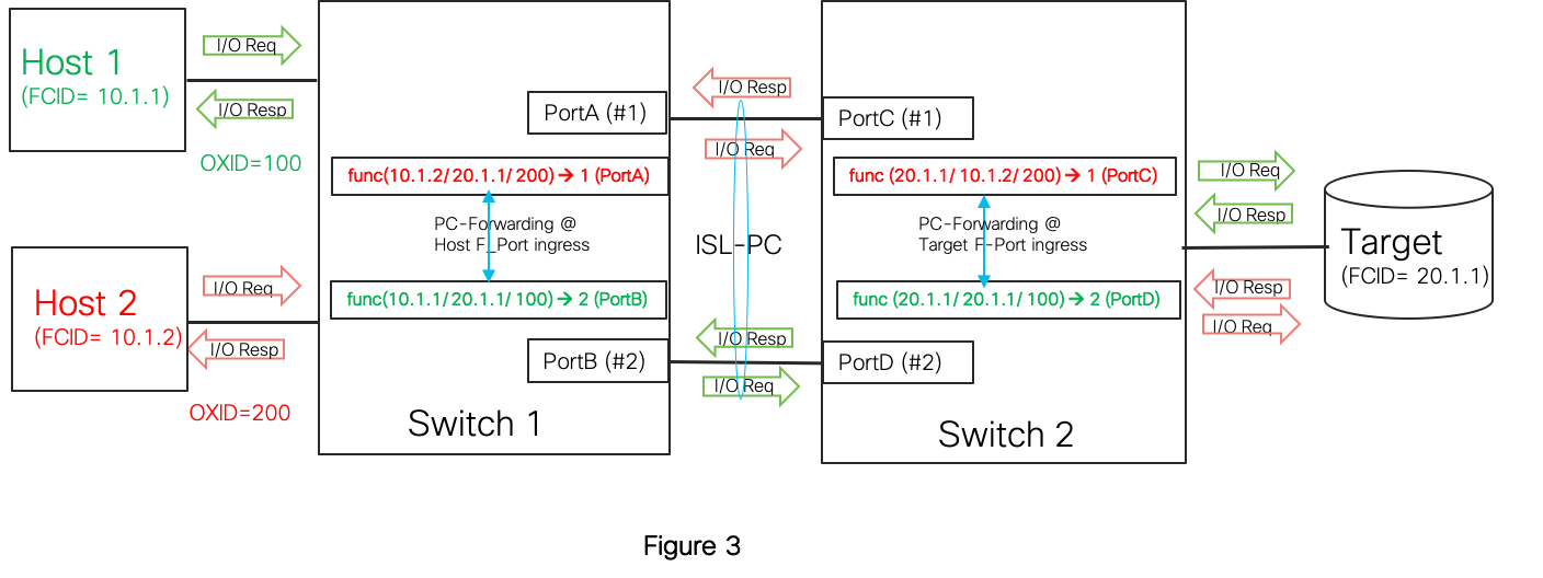
MDS switches implement an innovative scheme wherein a mathematical function is applied collectively on the SID/DID/OXID in the frame FC header to produce a number in the range [1 – <No of PC members>]. Since the SID/DID/OXID information is the same for all frames of the exchange, the output of the math function would be the same and pick the same member always. A rough real world analogy of this scheme would be using the index section of a book to look up the page numbers for a specific keyword. Further, the math function used has special properties that minimizes the chances of collision (multiple exchanges picking the same member simultaneously) and gives a good spread of exchanges across the PC members at any point in time.
Though not a requirement, the two MDS switches forming the PC can be set to use the same math function (default on MDS 97xx and T series fabric switches). Since the SID,DID,OXID combination values of the request and response frames of an exchange are the same, (SID/DID would be swapped in responses) either ends of the PC would independently pick the same member for the request and response IU frames of an exchange. This symmetric mapping ensures similar load distribution bi-directionally on the PC.
Figure 3 is simple example on how two I/Os from two hosts towards a target would be load balanced. Note that both I/O Request and Response of a given exchange pick the same PC member.
The MDS switches also supports an alternate LB scheme, which does LB at a per-SID/DID level (no OXID). But this scheme is sub-optimal and is not recommended in general.
3) Resiliency to link failures
Resiliency or redundancy in the context of an PC simply means that it is tolerant to PC membership changes when PC is actively switching traffic (Eg: unexpected link failures, admin addition of a new member etc). When a link fails, the LB scheme automatically adapts itself to exclude the failed member from future frame forwarding. The same happens when a member link is back up and frames would automatically start picking the link for frame forwarding.
But what if an exchange is in transit on a member and that member link unexpectedly flapped? Wouldn’t the subsequent frames of an exchange be rerouted to another member and then back to this member? Can this break IOD? The answer is a potential yes!
A simple way to ensure IOD is for the PC to drop all frames of exchanges that can be considered potential out-of-order delivery candidates. A frame drop may be preferred over out of order because most end devices can handle frame drops by detecting missing sequence counts for an exchange and after a timeout would discard those exchanges. However dropping frames is not the best of options in a “no-drop” FC switch.
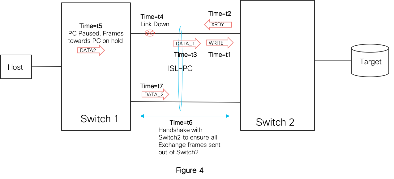
The MDS switches achieve maximum resiliency to PC member link failures by ensuring of IOD with least impact to traffic. The basic idea here is to pause frame transmission of frames that are destined to the PC that underwent a membership change. While the frames are held, the switch runs a handshake with the PC peer switch to ensure that all previous frames of impacted exchanges are flushed out from the neighbor switch. Once the handshake is complete (few us), the PC resumes the forwarding function and releases the frames on hold. Under heavy traffic conditions, the frame transmission halt could end up using all the ingress port buffers. But this only means the port would hold back B2B credit to traffic sourcing link peer without dropping frames.
Figure 4 shows operation when a member link goes down at time=t4 in the middle of a Write I/O exchange. While frame loss transiting the link when it went down is inevitable, note how an incoming frame DATA-2 is held in Switch1 till its guaranteed that all previous frames that made it to Switch2 are flushed out from Switch2. The DATA-2 frame is released from Switch-1 only at time=t7.
 When the PC membership change is a planned event (Eg: admin shut of a member port), MDS switches employ an even better scheme to ensure zero frame drop. In this case, it first ensures that no new incoming exchange picks the impacted member in the LB algorithm. It then handshakes with the peer switch till all previous in-transit exchanges are completed on the member at either ends before actually enforcing a shut action on the port and take it out of the PC.
Finally, Here is a question to tickle the engineer brain in you.
Given “N” ISL ports of same speed between two switches what are the tangible benefits of letting the ports run as individual links vs forming a PC? (Figure 5a vs 5b)

- The total bandwidth between the two switches would be the same in either case!
- Did you say better LB? No! In fact, MDS switches are capable of performing the same SID/DID/OXID based LB across either the members of the PC or a set of individual ECMP (Equal Cost Multi Path) links.
- Did you say resiliency? Partially right!
Huh! Think I took you for a ride till now on showcasing the benefits of a PC? Before you swear at me, let me elaborate on the answer 🙂
While all the earlier discussed benefits of higher aggregated bandwidth, load balancing, and link redundancy would apply for both the above cases, forming a PC offers additional benefits in an unexpected link failure scenario:
- Recall from FC basics that FSPF is a link state routing protocol of FC fabrics that tracks all ISLs and builds switch topology, computes and programs frame forwarding rules within switches. Since the PC is now acting as a single logical link from the FSPF point of view, individual member link failures does not impact the FSPF link state ensuring no route updates/recalculations/reprogramming anywhere in the fabric. This means better fabric resiliency on individual ISL link failures.
- The switch internal frame forwarding logic involves various stages in the ingress and egress pipelines of the ASIC. When a link failure is detected, frames that were already queued for transmission on the failed port would anyways have to be dropped. But when the link failure also involves route reprogramming, it takes some time and several more frames in various ingress and egress pipeline stages and already directed towards the failed port could be dropped. However since a PC member failure does not involve route changes, it results in about 30-40% quicker recovery and 50% lesser frame drops when compared to individual links. This means least disruption to traffic on ISL link failures.
I hope now you have a better insight into how frames are forwarded over an ISL PC and its real advantages. You should now know why its recommended to configure ISLs as PCs. If you have come across some other unique use-case with a PC, do let me know in the comment section below.
Even though I only considered ISL (E-ports) PCs, most concepts would apply to NPV/CoreSwitch (F-Port) PCs also. In fact an F-port PC would have significant advantages compared to operating as individual links. When operating as individual links, all the NPV switch connected end device traffic will be pinned to a specific link only due to binding of the device login to that link. Hence it would end up loosing out on both load balancing and link resiliency advantages compared to a PC. Also note that an F-port PC can be formed only when both the NPV and Core switch are Cisco devices only.
Since my main intention was only showcasing of advantages of an ISL PC between MDS switches, I did not cover details on FCIP/FCoE PCs formed with underlying GigE interfaces and trunking of multiple VSANs on a PC. I only briefly touched upon F-Port PCs.
Thanks for taking time to read. Will be back soon with another topic!
PS: A note of thanks to colleagues Fausto Vaninetti and Paresh Gupta for help in reviewing.
Authors