
I set out thinking I would write about SAN Analytics solution offering on Cisco MDS switches. But after a couple of lines I realized that readers would need a a strong understanding of the fundamentals before reading a post on SAN Analytics. So here I will present a dummies technical guide to Storage I/O and how it is mapped to Fibre Channel (FC) constructs to be transported over a FC-SAN. You can expect a 100% of Engineering and 0% of Marketing.
Wikipedia generically defines I/O as “the communication between an information processing system, such as a computer and the outside world, possibly a human or another information processing system”. In the Storage context, an I/O is a communication between the CPU/Memory of a compute system and a connected storage device. Even though that sounds very mundane, there is lots of stuff happening under the hood and lets us try to unravel it.
An I/O operation transfers application data from memory to a storage media in order to persist the data. Remember that CPU registers and memory are volatile in nature. So any application data that the CPU is not working on needs to be persisted to a storage media (disk/flash/tape etc) and I/Os are used to perform this function. A storage protocol defines the syntax and semantics of an I/O. The commonly used storage protocols are SCSI, NVMe. If the storage media happens to be external to the compute system you need an interconnect fabric and a transport protocol that defines how the storage protocol I/O constructs are sent over the underlying transport. The commonly used storage fabrics for this purpose are FC, Ethernet and the storage transport protocols are SCSI-FCP, NVMe/FC, iSCSI, NVMe/TCP etc. We focus only on FC and SCSI-FCP, NVMe/FC in this post.
The two primary I/O operations are Read and Write. There are few more types of I/O operations (like WRITE_ZEROs, XCOPY etc) that are infrequently used and we will not cover them here.
A Read I/O fetches “x” bytes of data from a specific offset in the storage media into memory. A Write I/O stores “x” bytes of data from memory to a specific offset in the storage media. Note that the offset here is a logical one (called LBA) and could undergo address translations before hitting an actual physical location in the storage media. The “x” here is what is called as an I/O Size. The I/O sizes are in the range of 512 Bytes to a few MBs. The sizes are always in multiples of 512B due to historical sector size of 512B on hard disks. It is an Application or the File System that decides how the data destined for storage is split into I/O sizes. A majority of applications (~ 70%) perform short I/Os in the 512B to 8K range. You might wonder: How complicated can these short Read and Write commands get? Please hold on to that thought till you get to the end of this post 🙂
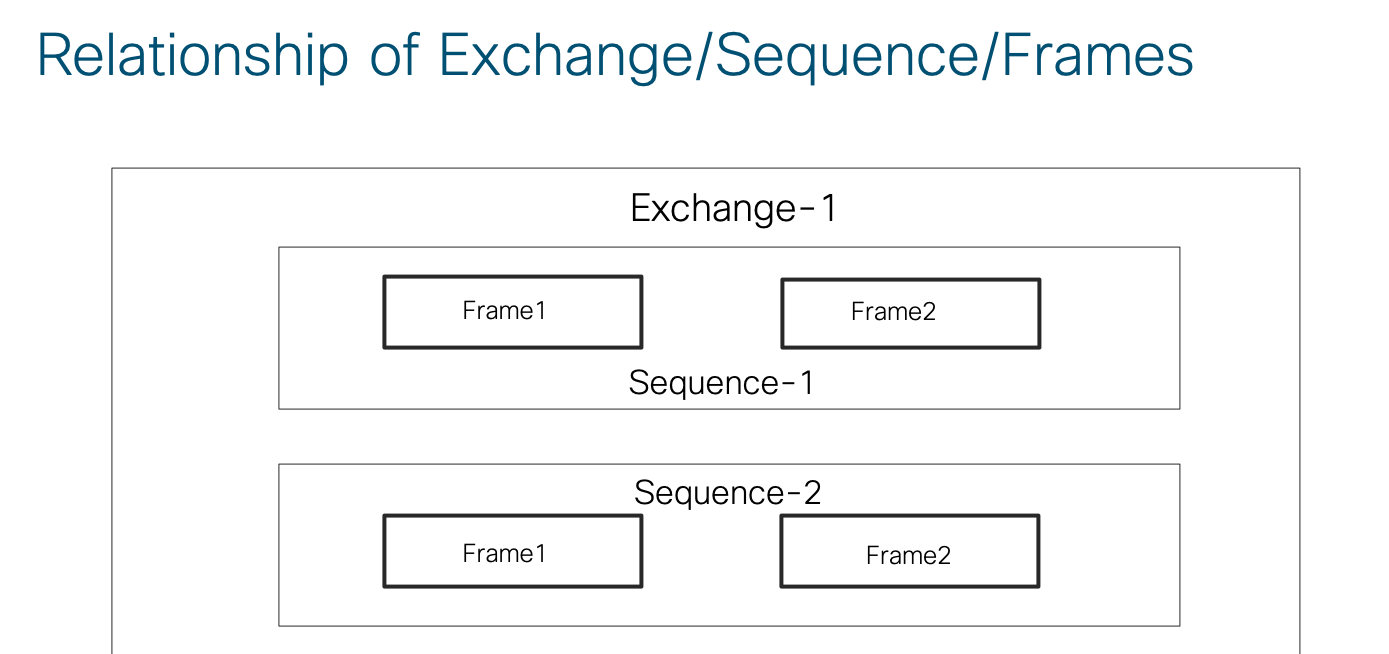
A FC fabric is designed to transport storage protocols. It has specialized constructs called Exchanges and Sequences which are tailor made for I/O operations. An I/O operation is fully contained within an Exchange. An Exchange consists of multiple sequences and a sequence consists of multiple frames. The relationship is pictorially shown below.
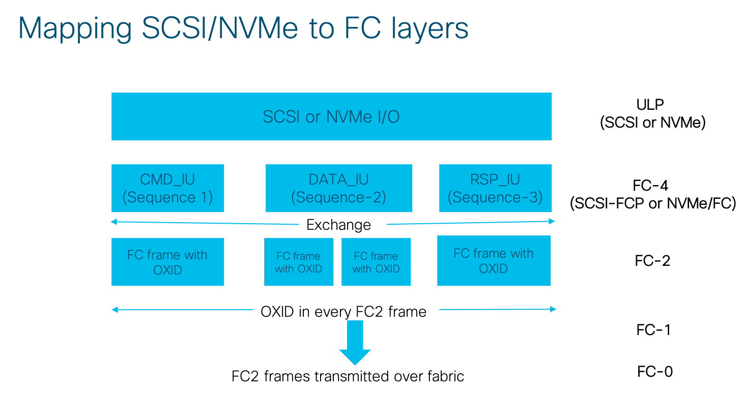
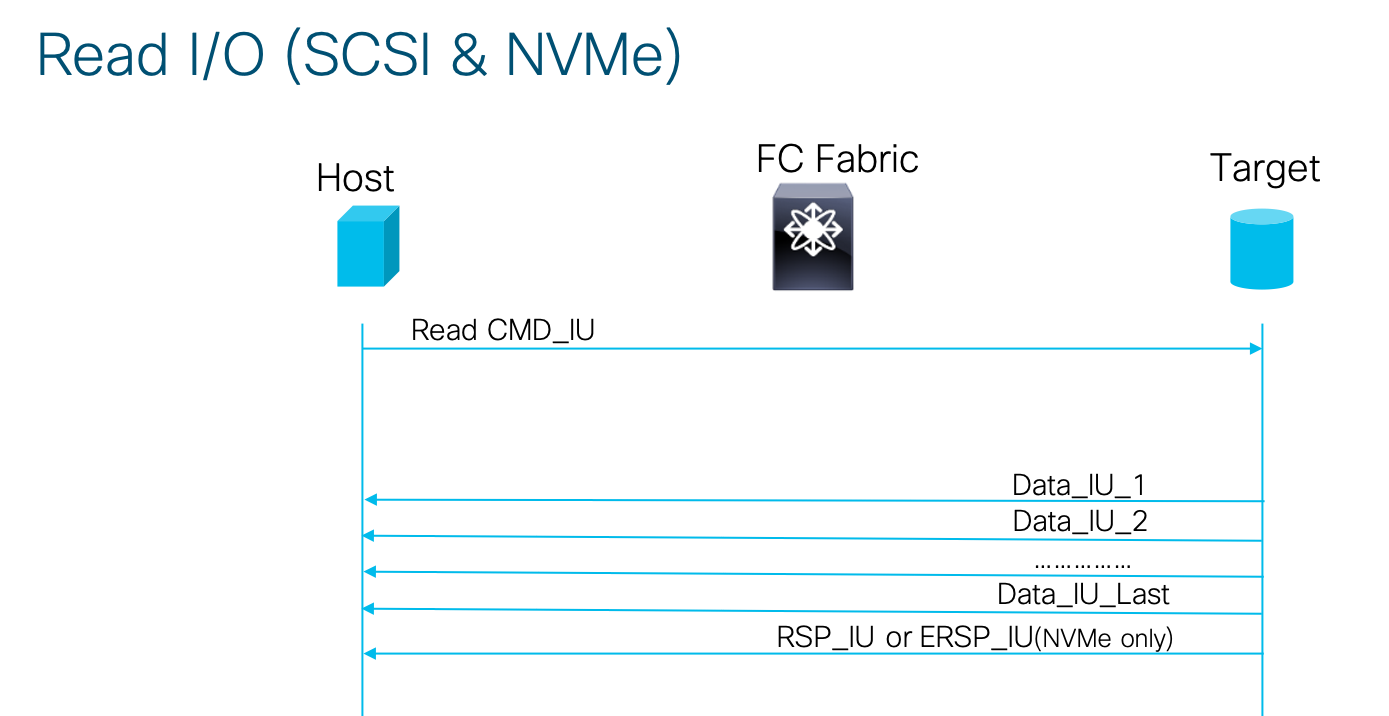
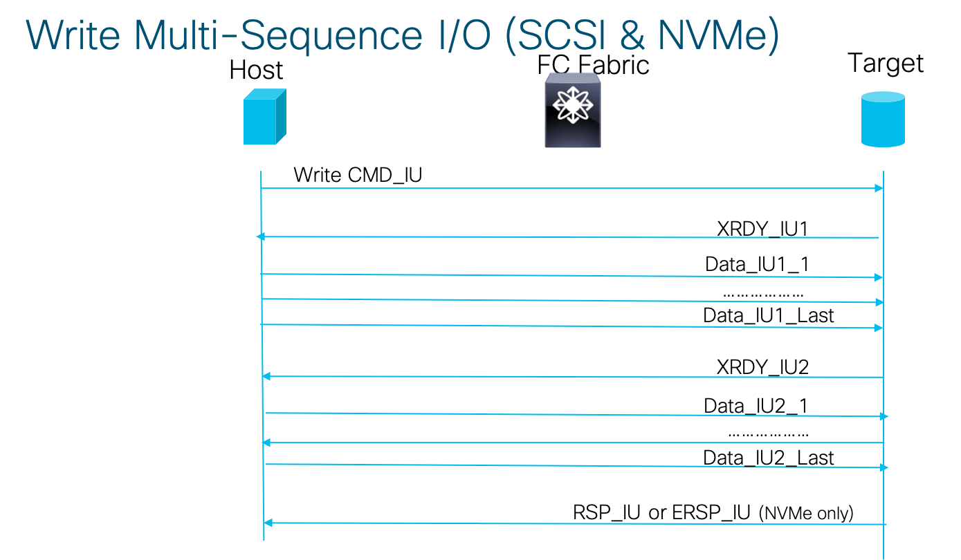
Let us now dip our feet a little deeper into what exactly transpires when I/O happens over a fabric. Lets look at SCSI over FC (referred to as SCSI-FCP) first. SCSI-FCP defines IUs (Information Units) for performing I/O operations as: CommandIU (CMD_IU), DATA_IU, TransferReadyIU (XRDY_IU), ResponseIU (RSP_IU). An I/O mapped to an Exchange consists of multiple of these IUs and every IU is mapped to a Sequence. An OXID (Originator ExchangeID) is contained in the FC header for every frame in an exchange and the (Host/Target/OXID) tuple uniquely identifies an Exchange in the fabric. A SequenceID present in the FC Header for every frame in a sequence uniquely identifies a sequence (IU) within an Exchange.
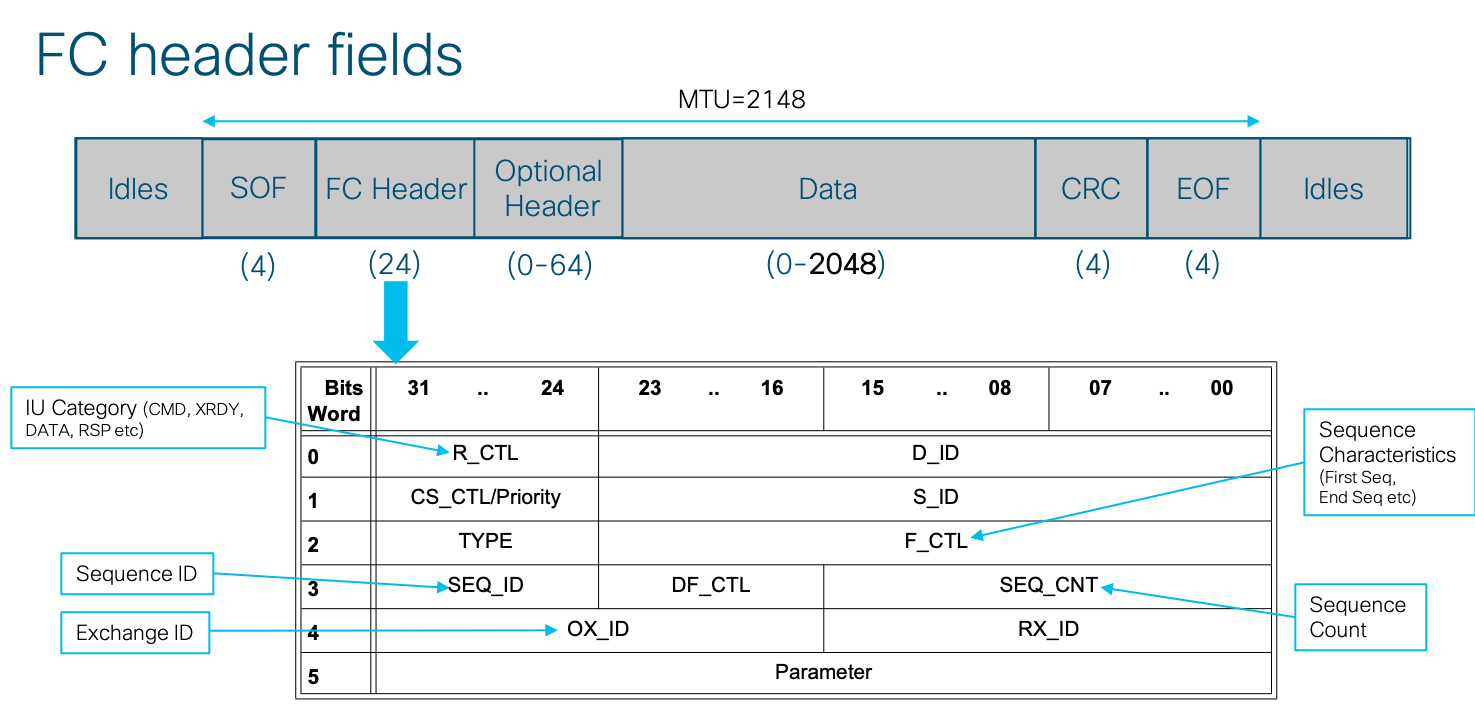
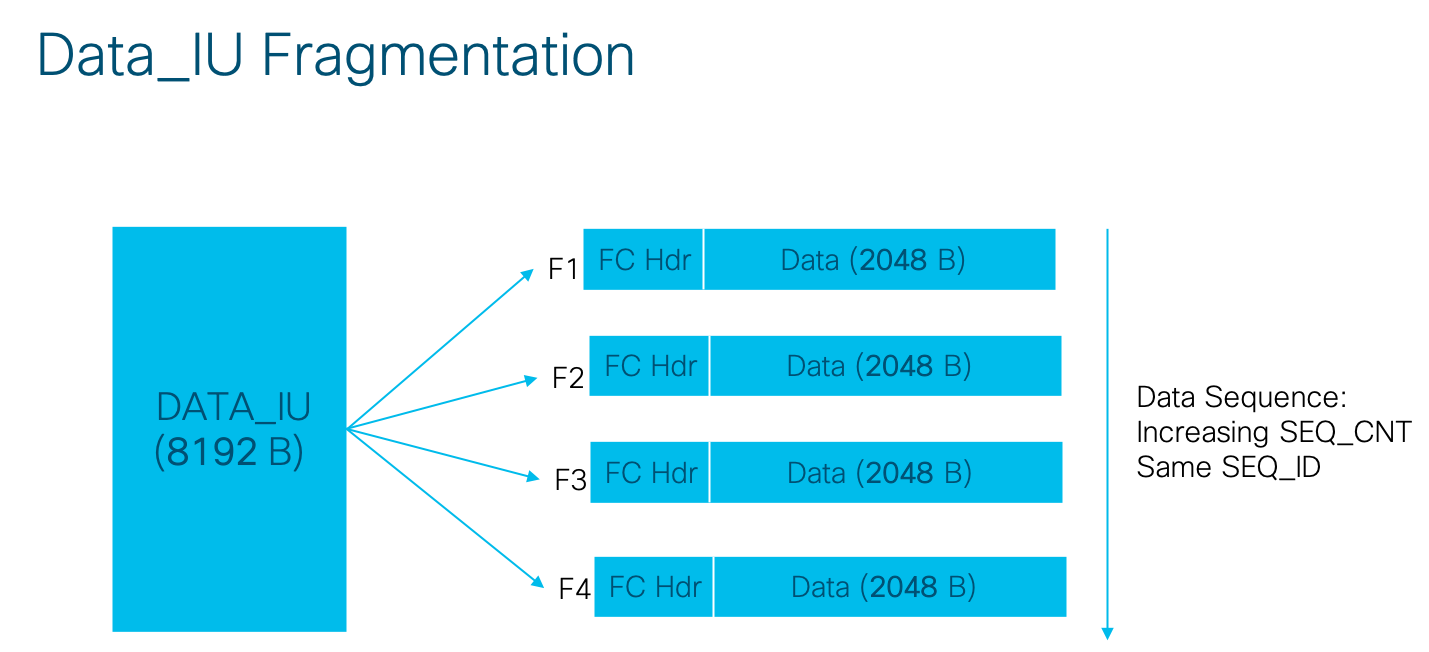
The MTU of FC is fixed at 2148B, with 24B header and 2048B (2K) payload as shown below. The FC header has fields like Source_FCID, Destination_FCID, TYPE, R_CTL, F_CTL and OXID as shown below. Each IU is identified by a specific R_CTL value and is packed into the 2K size FC frame payload. The IUs greater than 2K (usualy the DATA_IUs) are is split into multiple FC frames. The payload size of 2K allows a clean alignment of common I/O sizes to FC frame boundaries as shown by an example below for a common I/O size of 8K. An IU can be a Request or a Response (from host perspective) as indicated by the F_CTL field in the FC header. The sequence count field increments for every frame of a sequence. SCSI FCP uses TYPE = 08h in all the frames of the exchange.
Lets now look at each of these IUs in a bit more detail:
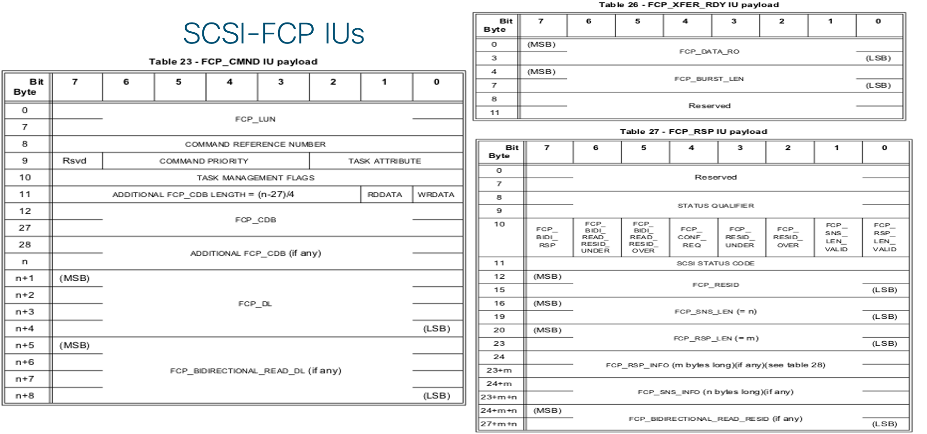
- CMD_IU is used to carry a command request and is identified by a R_CTL=06h. A CMD_IU is typically a single frame sequence, always transmitted by a host. The important fields of a CMD_IU are:
– LUNID: The LUN to which the I/O is destined
– CDB (Command Descriptor Block): contains Opcode (Read/Write), LBA etc.
– FCP_DL: indicating the I/O Size - XRDY_IU indicates preparedness of the sending target to receive part or all of the data of a Write I/O operation and is identified by a R_CTL=05h. The target allocates buffer/cache resources (typically DMA) based on the size in the FCP_DL field of the Write CMD_IU. Its a single frame sequence transmitted by a target.
The important fields of XRDY_IU are:
– Burst Length: Number of bytes to be transferred in the following DATA_IU.
– Relative offset: Offset relative to the first byte of the data series for the Exchange. - DATA_IU transfers the data as requested in the CMD_IU and is identified by a R_CTL=01h. There can be one or more DATA_IUs sequences used to transfer all the data. When more than one DATA_IU is used, the PARAMETER field in the FC header is used to ensure the data is reassembled in the proper order. It can be transmitted by either host or target depending on if it is a Write or Read I/O. The DATA_IU payload consists of a sequence of word aligned data bytes.
- RSP_IU indicates the completion of an I/O operation with the final status and is identified by a R_CTL=07h. There is one RSP_IU for every CMD_IU and is always transmitted by the target. The important fields of RSP_IU are:
– STATUS_CODE indicative of the status of the I/O operation.
– Flags indicating more details in case an error happened.
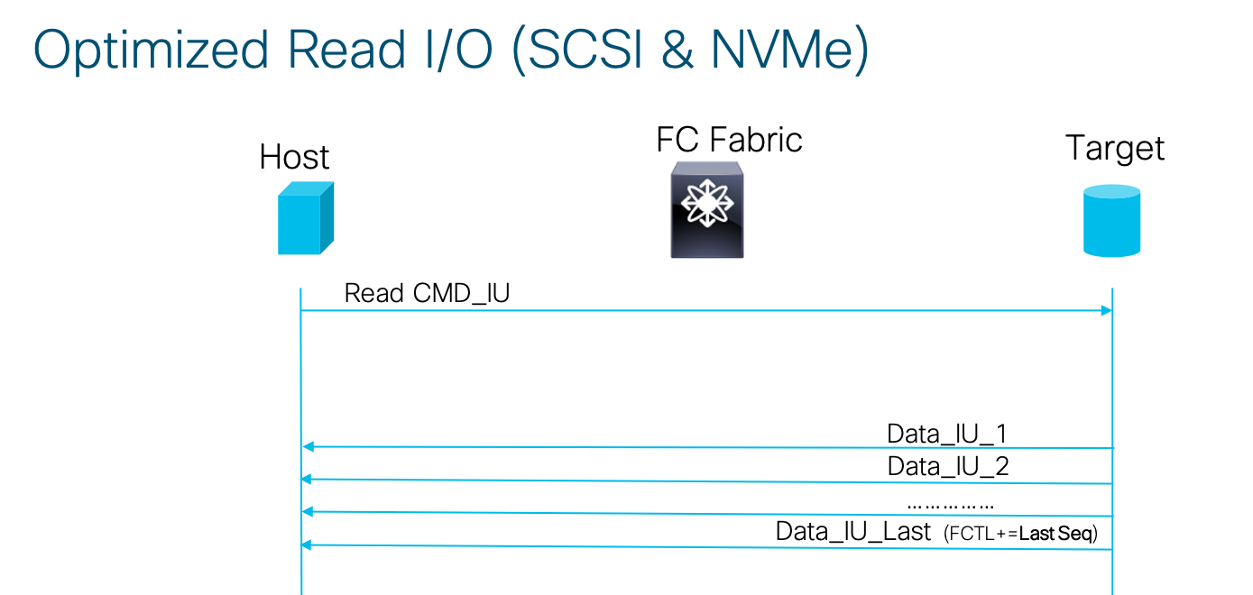
Some HBAs implement an optimization where the RSP_IU for a success case is skipped with the SUCCESS response indicated in the last frame of the DATA_IU itself (a concept borrowed from iSCSI).
The below diagram shows the frame formats for each of the above IUs (from SCSI-FCP Spec):
Let us now take a look at IUs of the NVMe/FC protocol. The NVMe/FC standard defines how the NVMe protocol is mapped to FC fabric. It would be natural to expect that a new FC-TYPE defined with a parallel set of IUs for I/O operations. However this would mean the existing FC switching hardware and FC HBAs with acceleration logic designed for TYPE=SCSI-FCP(08h) would have to change to accommodate NVMe/FC. Hence the FC-NVMe standard plays a small trick to ensure existing switching and HBA hardware accelerators could still work with FC-NVMe transparently. The NVMe/FC was defined to reuse the TYPE=08h and the same set of SCSI-FCP IUs (same R_CTL values) for NVMe I/O operations. To distinguish a SCSI FCP I/O vs NVMe/FC I/O, a NVMe signature was added in the CMD_IU. The 8 Byte LUN field in CMD_IU is not used by NVMe. So the first two byes of the LUNID was defined as a NVMe signature with a value FD28h in the NVMe CMD_IU. This LUNID value would fall in the category of a reserved LUNID and would never be used by SCSI-FCP either.
The NVMe_CMD_IU with the first 2 bytes as FD28h is followed by NVMe specific frame format. It may be noted that FD28h signature was added for NVMe CMD_IU only and the NVMe DATA_IU, NVMe XRDY_IU looks exactly like their SCSI-FCP counterparts. This definition of NVMe/FC IUs ensured that a new storage protocol could be supported on all legacy FC infrastructure.
However there are some notable differences of NVMe/FC with respect to I/O operations:
- The RSP_IU in NVMe/FC is defined to be used in success responses only and is defined as a 12 Bytes of 0s. This fixed byte pattern allows for faster processing of success responses and helps the lower latency cause of NVMe. For failure responses, a new ERSP_IU (Extended response) is defined with a response result. The ERSP_IU is also used for a periodic NVMe level flow control (even when with a success status) and is out of scope of this discussion. The ERSP_IU uses a new RCTL=08h.
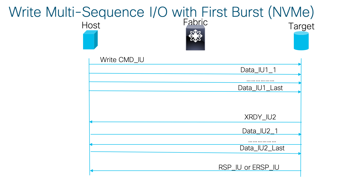
- NVMe/FC also introduces the concept of a First Burst (FB) Write. With FB, the host may choose to perform Write I/O by sending the first DATA IU without a preceding XRDY_IU. The target may accept or discard the first NVMe DATA_IU. If the target accepts the first NVMe_DATA IU, then the target uses XRDY_IU(s) to request the transfer of any remaining data for the Write I/O. If the target discards the first DATA_IU, then the target shall use XRDY_IU(s) to request retransmission of the data for the Write I/O originally sent in the first DATA_IU as well as for any remaining data for the Write operation. The advantage of the FB scheme is that for shorter Writes, the I/O can complete faster without waiting for an XRDY_IU. This also helps the cause of lower latency for NVMe I/Os.
The NVMe/FC IU formats are shown below (from the FC-NVMe Spec):

The below diagram shows the I/O translations in the various layers of the FC stack. We can see how the SCSI/NVMe (upper layer protocol) I/O is translated into IUs and eventually into Exchanges/Sequences at the FC-2 layer before the frames are sent out for transmission by lower layers on to the wire.
Now that we have understood the various IUs that constitute an I/O, let us finally look at how all these come together to actually perform an I/O operation in a pictorial manner:


I hope now you have a fair understanding of Storage I/O operations and how they actually translate into frames when transported over a FC fabric. In a future post I will try to use these concepts as a foundation to explain Cisco’s latest offering of SAN analytics solution on 32G MDS switch fabrics.
As always comments are welcome in the below section.
Authors
3 Comments
Thank you so much for this article! It was a great read and it helped in better understanding how SCSI & NVMe work!