
Following up on our previous article: How to Start Using CML for Free – Step by Step Guide, we will continue our CML series by showing you how you can start designing your first network. Let’s start! To view each image full size, please click on it.
- Create a new lab:

- Rename the lab:

- Click on your lab and you will access the design window:

- Drag and drop the devices you want into your network:

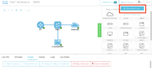
- Connect the devices by clicking and hold the blue button and attach it to the needed device:

![]()

- Then you can either select the next available interface or a specific one:

- To validate what ports were used to connect the devices, click on the device and go to the connectivity tab:

- To verify how many interfaces a device has, click on the “Interfaces” tab on the router there you can see that by default it have only 4 interfaces:

- You can add more interfaces until reaching the maximum of 15 (depends on the device):

- Also, you can remove interfaces. Keep in mind that adding and removing interfaces from a device needs to be done before you initialize them.

- Click on the devices and rename them:

- Now you have all your devices with the name you wanted:

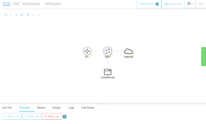
- Click on the simulate tab and start the lab:

- When all the devices have a green dot means they are ready:

- You can start configuring the devices in two ways: 1) With the console tab

- Access them via SSH with any program you prefer, for example, SecureCRT, first you need the information you used to connect to the lab previously:

- Open SecureCRT and use that information to connect:


- When connected you will see the following screen:

- Type the “list” command to display the devices you can access:

- To access the devices type: open /<Lab ID>/<Node ID>/<ConsoleLine>. Example: open /1cef59/n2/0

- After the device finished initializing you will see the prompt line to start configuring:

- If you want to have different tabs for all the other devices, you just need to clone the session and connect to the node you want:


- Rename the tabs to have them organized:

- Proceed to add some initial configuration:

- As you can see you didn’t add an IP address instead you use DHCP, that’s because you added an external connector to the topology and it will work as a DHCP Server, DNS, and will simulate the Internet.

- You can access the Linux box with the following credentials
Username: ubuntu
Password: cisco

- To save the topology and the configuration of the devices, click on the node tab, select all the devices and click on “Extract Configs for Selected”:

- Then go to the top right corner and click on “Download Lab”:

- It will create a .yaml file so the next time you want to continue working on this lab, you can just load it and continue from where you left.
![]()
- To load this file, click on “Import Lab” at the top right corner

- Then look for the .yaml file and upload it

- The topology should be the same we had
- Validate that the configuration is in place, like the hostname and IP address via DHCP:

With this, it doesn’t matter if you only reserve for up to 4 hours your CML environment, because when the time is over you can reserve a new session and upload your topology and configs to continue from where you left. Now start your own lab and start playing with all the features so you can prepare for certifications, learn new technologies, or simply having fun!
Authors

Comentar